BASIC INFORMATION ABOUT LIFTS
- Lift definition
A lift is a system permanently installed that serves for vertical (or in the direction smaller than 15% from perpendicular) transport of persons or goods in lift cars or on platforms. - Basic dimensions

Headroom: a part of the shaft between the level of the highest stop and the shaft’s ceiling.
Travel: the length of the cabin’s travel between level of the lowest and the highest stop.
Pit: a part of the shaft below level of the lowest stop.
- Rated load.
It is a load in kg that has been assumed for the drive calculations. The calculative load is the value that has been assumed for strength calculations of key bearing elements and usually it is the weight of maximum number of persons who a lift holds on a lift car defined area. There is a close relation between the load, a maximum number of persons and the area. For example, the load of 630 kg is the number of maximum 8 persons that is limited by the lift cabin area equal to 1,54 m2 (1,1 x 1,4 m). In case of passenger lifts the nominal load is equal to the calculative load whereas in case of goods lifts it is admissible to reduce the nominal load in relation to the calculative one resulting from the lift cabin area. For more information see EN 81-1/-2 standards. - Lifts classification depending on drive
Hydraulic lifts : the lift drive unit is composed of a tank, a hydraulic pump and an electric motor and starts a piston that through a direct ratio of 1:1 or through an indirect one of 1:2 (a rope pulley and ropes) drives the lift cabin.
1:1

1:2 (with indirect roped drive)

Lift with 1 piston Goods-passenger lifts with 2 pistons
The hydraulic lift’s machine room is not adjacent to the shaft and can be located in a distance from zero to several or even a dozen of meters from the shaft. Most frequently it is a free standing cabinet (so called machinery cabinet) or a separate room (a traditional machine room). There also exist hydraulic lifts without a machine room with a drive situated in the pit.
Traction lifts : the lift drive unit that is composed of an electric motor and a friction wheel coupled with it, drives the ropes connected with the lift car frame and a counterweight. There is distinguished a direct drive of 1:1 and an indirect one of 2:1 and 4:1 used in traction goods-passenger lifts.
1:1 2:1

- Essential lift componentsCabin: a lift unit designed for transportation of persons and/or goods.
Shaft: a space in which the lift cabin moves. The space is as a rule housed with pit bottom, walls and ceiling.
Machine room: a room in which the drive unit (or units) and the connected equipment are situated, e.g. control elements.
Drive unit: a unit that contains motor that drives a lift. In traction lifts it is so called traction machine and in hydraulic ones it is a set with a motor, pump and valve block.
T-guides: rigid elements that secure guiding of a car frame and a cabin.
Car frame: a rigid construction that holds the car and travels in the guides.
Counterweight: a separately guided mass that partly counterbalances the cabin and secures ropes pressure to a driving pulley.
Controller: a unit that controls the lift travel.
Piston: a lift component that uses a working medium for a plane motion. The piston is composed of a cylinder and a ram. There are also single or multistage pistons so called telescopic.
- Lifts classification depending on application:Passenger lifts – serve for transportation of persons.
Hospital lifts – are designed for transportation of persons and hospital beds together with medical equipment and personnel. They are characterized by accurate minimum cabin dimensions and door width as well as some functions such as “privileged travel”.
Vehicle lifts – are designed for transportation of vehicles. They are characterized by accurate minimum cabin dimensions and door width.
Goods-passenger lifts – are designed for transport of goods and persons accompanying the goods.
Goods lifts – is a group of lifts without a right to enter for persons. It is obtained by strict restrictions regarding the usage or by reduction of car dimensions (so called “small goods lifts”).
- Machine room
Special room – accessible only for the authorized persons – which contains the lift drive unit and equipment related to it, e.g. lift controller. - Shaft
The shaft means the space in which a lift car moves. The shaft has usually a pit, walls and a ceiling. Depending on the lift type, in the shaft can be situated a drive unit, a counterweight and controller. - Cabin
A lift’s unit serving for safe transportation of persons and/or goods.
1-opening – a cabin with a single entrance.
2-opening – a cabin with 2 opposite entrances.
Angle cabin – a cabin with 2 entrances situated at an angle of 90°.
Three-entrance cabin – a cabin with 3 entrances. - Doors
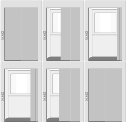
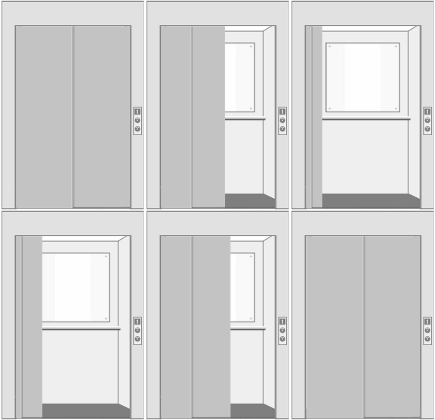
Lift doors are divided into landing (shaft) doors and cabin ones. The doors exist in two basic variants: central and telescopic (two or multipanel).Central door – during opening / closing, the panels move in opposite directions.
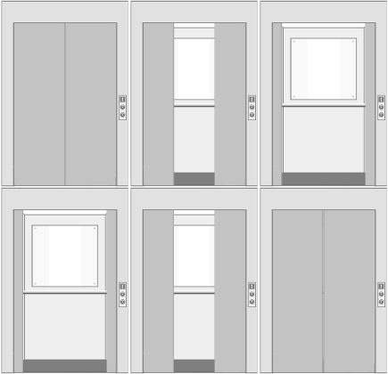
Telescopic door – during opening / closing, the panels move in the same direction.
Swing doors – operated manually and are no longer used in newly designed lifts.
- Standard lifts
These are lifts of repeatable components and the shaft horizontal dimensions (width x length), and differ only in the number of stops and travel height. Thanks to the above fact, architects have easier task during a shaft designing and the risk of error is reduced. - Non-standard lifts TML
(Tailor Made Lift). These are lifts of unrepeatable features and that is why they are designed individually to a given order. For example, lifts in existing shafts of atypical dimensions, panoramic with glass cars or lifts with 2 entrances to a car at an angle of 90o and even of 3 ones. - Lifts designed for new buildings
The lifts of full dimensions of shaft, pit and headroom. - Lifts designed for existing buildings
Considering the shaft’s existing environment it is admissible to reduce the pit or the headroom, however with use of additional safety devices for lift fitters and maintenance technicians. For more information consult PN-EN 81-21 standard. - Lifts for disabled persons
The building regulations require adaptation of passenger lifts for disabled persons. The basic requirements are minimum car dimensions (width x length) 1,1 m x 1,4 m, the door width of 0,9 m, push buttons marked with the Braille alphabet and voice information. Detailed requirements are defined in PN-EN 81-70 standard. - Collective function – enables storing of a lift call commands in a memory by users and their execution by picking up the passengers going in the same direction. In multi-family apartment buildings a collective down is used (a lift picks up passengers going to a ground level) while in office buildings a collective up/down is usually applied. During going up a lift picks up successively passengers who want to go to higher floors while when going down it picks up persons who want to go to lower floors.
Reaction to electricity failure – in case of electricity failure (blackout) a lift should reach a nearest or lowest stop and open doors automatically to free passengers. Unfortunately, most of manufacturers use this solution as an option at high extra charge.
Operation in group – lifts that are located in a close neighborhood should operate in a group and a call regards one lift – that one which is closer to a calling person.
- Comparison of hydraulic lifts with traction ones – advantages/disadvantages
Feature/function Hydraulic lifts MRL-type traction
(with power unit in the shaft)Shaft The shaft is material-saving with minimum one reinforced concrete wall. Main forces are concentrated on the pit bottom. The shaft dilatation is not required even in apartment buildings. Small dimensions in relation to the car. The shaft is massive, material-consuming, holds (the upper engine room in case of traditional lifts), a drive unit, a counterweight and a car. In case of neighbourhood of apartments, the shaft dilatation is recommended. Big dimensions in relation to the car. Construction Simple. Small number of parts – including rotating parts. No counterweight. Low lift weight: 40-60% lower than lifts without engine rooms. Complicated construction. Many parts – including rotating parts: delivery wheels, bearings. Big length of repeatedly bent carrying ropes. The lift high weight in relation to the load. Purchase cost Lower by approx. 20-30% for a 2-5 stops lift. Relatively high for lower travel heights. Installation / operation Exceptionally quick, safe, uncomplicated and cheap installation. Efficient repair and replacement of components. Complicated installation requiring highly qualified personnel. It is usually 2 times longer than in case of hydraulic lifts. Complicated repair and replacement of main units and ropes. Operating costs Low maintenance and spare part costs. High maintenance costs and very high costs of spare parts. Speed Usually 0,63 m/s. High, usually 1 m/s and higher. Lift durability Long life, approx. 2 times longer. Moderately long. Connection of power Approx. 2 times higher. Several kilowatts. Electric energy consumption Comparable or lower. A hydraulic lift goes down with switched off main engine. During the lift stop the energy is consumed by the car main lighting. High energy is needed to move the counterweight in case of the car unbalancing (empty or fully loaded). During the lift stop the energy is consumed by a frequency converter (so called inverter) and the car lighting. Reaction to power failureLoad < 2.000 kg Travel to the lowest stop by gravity and door opening. A low-capacity battery required e.g. 7Ah. Battery which supports the voltage in the electronic control unit is fully sufficient.Load 2.000 – 12.500 kg
Travel to the lowest stop by gravity is supported by the 7Ah battery. To open large and heavy doors an UPS of 600 – 1000 VA is sufficient.Easy release of passengers in case of the emergency power system failure.
Load < 2.500 kg Travel to the nearest stop. Required a UPS device of 1000 – 3000 VA power. Monthly checking of voltage level highly recommended.Load 3.000 – 5.000 kg
Required a battery power station or a motor power generator to move cabin and open door.Complicated, difficult and time-consuming release of passengers in case of the emergency power system failure.
Safety High.
No massive units above the car.
The machine room is usually separated, far from the lift working units.Medium. Higher risk for personnel during installation, repairs and maintenance. Ground tectonic motions or earthquakes can cause the construction fall down due to the massive elements located in the head room (traction machine or counterweight). Such cases are reported in the seismic areas. A specially protected lift construction is required. Noise emission The shaft does not usually contain drive units. Noise is emitted in a closed engine room far from the rooms in which people stay. The power unit and control unit situated in the shaft makes the noise emission going easier through the building. It can be particularly bothersome in apartment buildings because not all drive units are silent. Ecology Environment friendly. Exceptionally material-saving shafs and the lift low weight as well as small number of parts – means lower energy needed for production. Hydraulic fluid undergoes 100% recycling after 5-10 years of operation. The massive shafs and units: a massive traction machine and counterweight, long ropes, many parts – means higher energy needed for production. In drives are frequently used so called permanent magnets that require much energy during raw material exploration and in the production process what has a very negative environmental influence. - Noise emission
Every lift system emits noise during operation. However, use of a suitable lift type, the shaft correct construction and its location can considerably reduce noise emission in a building and inconvenience for the people staying in.
Hydraulic lifts are characterized by low noise level thanks to the drive unit location (power unit) outside the shaft: in a prefabricated engine room or in a separate room. It is worth to pay attention that the drive works only during going up. Going down is executed by the gravity force with the power unit off.
Traction MRL-type lifts without a machine room have drive in the shaft. This makes the noise emission going easier through the building. To reduce the noise inconvenience, the lift shafts are separated from the apartments with additional shaft concrete walls (dilatation) or the lifts are located in the central part of a staircase. Both methods waste a building internal space and require an additional energy-consuming heavy concrete construction.

Travel up Travel down
Hydraulic lift with typically located power unit.

Travel up / down
MRL-traction lift without machine room and power unit located inside the shaft.
